Article: Vulkan Ray Tracing
How ray tracing works in my engine, with a focus on software architecture.
Overview
I’ve been working on implementing hardware accelerated ray tracing with the ultimate goal of adding real-time reflections and global illumination to my engine. To aid in my understanding, I implemented a simple path tracer that I can use as a reference for my rasterized renderer. There are a lot of good articles on these topics, and also on neccesary concepts like Monte Carlo integration, so I thought I’d talk about something I haven’t seen discussed much: architecting the ray tracer.
Part 1: Pieces and Goals
First, let’s talk about what we need to get ray tracing working. I’m going to use Vulkan terminology, but I’m sure the concepts are similar for DX12. To represent our scene, we need two kinds of structures: top level acceleration structures and bottom level acceleration structures.
Bottom level acceleration structures (BLAS) are how you store your geometry. They are typically collections of triangles that are preprocessed in an implementation defined manner. The general advice I’ve seen for these is as follows:
- Use as little detail of an LOD that you can get away with. I don’t have LODs yet, so this isn’t an issue for me.
- You want to minimize open space in a BLAS. Geometry should be kept as close together as possible.
Top level acceleration structures (TLAS) are how you represent the “scene.” That is, you have instances of bottom level acceleration structures (meshes) placed within the top level acceleration structure. The general advice for these is as follows:
- Cull as many objects as possible. The fewer instances you have, the faster it is to trace.
- Avoid overlapping instances. Rays have to check each instance they overlap with.
Then, we have the actual shaders used. There are four kinds of shaders.
- Ray-Gen: This is the shader that dispatches rays. If you read my mesh shading article, it’s similar to how the task shader works in that it dispatches the rays and they run separately from the ray gen shader. Unlike the task shader, the results from the rays intersection tests are later used in the ray-gen shader. You get the results of a ray hit via a payload structure. This is where you would typically output to an image.
- Closest-Hit: This shader is invoked when a ray hits an object. Specifically, it is called for the ray intersection that is closest to the ray origin. You use this shader for opaque geometry.
- Any-Hit: This shader is like the closest-hit shader, but it is invoked for each intersection. I haven’t used these yet, but I’m aware they are used for transparent and alpha-tested geometry.
- Miss: This is the shader that’s invoked when the ray misses everything. Typically, you’d have it output your sky color.
Lastly, we have something called a “Shader Binding Table (SBT).” This is a structure that holds pointers to all the shaders. Each instance in the TLAS holds an index for the SBT entry it is using. This is required because a ray might hit any object in the scene, and objects are allowed to have arbitrary hit shaders, and thus a ray might invoke any arbitrary hit shader.
This is really all you need to get rays traced. The goals I set when I started implementing the ray tracer were as follows:
- It should be easy to add new material types.
- It should handle meshes with any number of vertex attributes.
- It should be easy to experiment with different TLAS culling strategies.
- It should “just work” and not require a ton of fine tuning to get “ok” performance.
With all that in mind, here’s what I came up with.
Part 2: BLAS and TLAS
BLAS’ were easy enough to set up. I don’t do anything fancy. Each mesh gets its own BLAS which is baked as soon as the mesh is loaded. The renderer amortizes this over multiple frames to prevent stuttering. I also made sure that each meshlet within a mesh is considered its own “geometry.” The idea is that each meshlet should have its own AABB to be tested against, but I’m not sure if my hardware is actually doing this (the actual BLAS and TLAS data structures are opaque.)
TLAS’ were also not that difficult. The Vulkan API allows you to have instances within the TLAS be pointers into another buffer, and I already have all my object data in a big buffer. So, I fill out the TLAS as follows:
- For each object in the scene, I run a closure to check for culling. The closures are easily modifiable to do culling however I want, but currently I’m culling based on bounding sphere projected radius as described in this presentation by EA on ray-traced reflections in Battlefield V.
- I resize the TLAS, scratch buffer, and object pointer buffer to fit the number of objects that passed culling.
- I write in object data pointers that passed culling.
I modified my GPU-side object data structure to include the Vulkan TLAS instance as a header and added all my other data after it. The result is that each object instance occupies 128 bytes in memory and can be used as a TLAS instance. This setup allows for a single function call to generate a TLAS with whatever objects I want. Pretty convenient!
Part 3: The SBT
Alright, this is where the fun begins. My single most important goal is the ability to add new material types quickly. With that in mind, it was critical to get my SBT set up in a way that supports this goal since the SBT contains the code for all the materials. So, here is what I came up with.
First, the “Ray-Gen” and “Miss” shaders are unique to the particular ray tracing pipeline I’m creating. Or, in other words, they’re the same for every material type. With that in mind, I simply put them as the first two elements in the SBT.
Next, we consider the “Hit” and “Any-Hit” shaders. They’re unique for each material, but not only that, they’re unique for each combination of rendering mode and vertex layout. They’re unique for different rendering modes since the ray logic for opaque, alpha tested, and transparent geometry is different. They’re also unique for each vertex layout since you might not have UVs, meaning you can’t sample textures. I require all meshes to have positions and normals, so the total number of combinations is NUM_RENDERING_MODES * (1 << (NUM_VERTEX_ATTRIBUTES - 2)). Conveniently, the hit pipelines within the SBT don’t need to be unique, so if two combinations have the same code, we can reuse their pipelines.
So, the SBT ends up looking something like this:
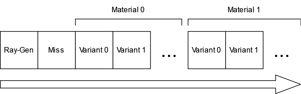
So, as you can see, the “Ray-Gen” and “Miss” get the first two slots, then each material (indexed by their unique ID) gets a whole bunch of slots for each combination of rendering modes and vertex layouts. The number of variants a material has is the same for all materials, so lookup for the correct SBT entry is a trivial base + (material_idx * variant_count). The renderer automatically detects when new materials are created and recreates the SBT for all ray traced pipelines as needed.
Additionally, I updated my material system to handle “ray-traced passes.” Essentially, a material can define unique pipelines for each kind of ray-traced effect. For example, global illumination doesn’t require very high detail textures, nor does it require normal maps, so I could have a pipeline for the “GI pass” that uses the lowest detail mip and doesn’t sample from the normal map. Reflections, however, do require normal maps and decently high resolution textures since you will be seeing the reflected objects in high detail. So for the “reflection pass” I can allow normal maps and higher detail textures.
Conclusion
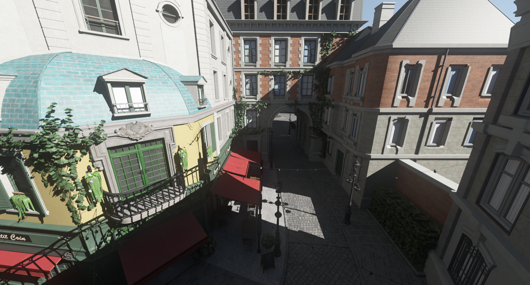
And that’s it! With this setup, I accomplished all the goals I set out to achieve. To test it, I created the simple path tracer I mentioned in the introduction. The image above is the output of the path tracer on the Amazon Lumberyard Bistro scene. You’ll notice that the foliage looks weird since I haven’t implemented the any-hit shader yet. Also, if you’re very familiar with this scene you might notice some geometry is missing (some potted plants, a manhole cover, etc). This is expected, and is the result of the culling algorithm I’m using. My next step for this is going to be adding reflections and global illumination. For reflections, I’m going to investigate the hybrid screen-space and ray-traced approach in AMD’s FidelityFX Hybrid Reflections. For global illumination, I’m trying to decide between a probe based approach like DDGI or surfels like in EA’s SIGGRAPH 2021 presentation. I might even end up with a hybrid solution that uses both, possibly by sampling surfels for nearby geometry and sampling directly on probes for distant geometry. I’m hesitant to dive too deeply into screen-space radiance caching as used in Epic’s Lumen or AMD’s GI-1.0 since they seem to rely heavily on screen-space temporal reprojection which I’m trying to avoid because of quality concerns.