Article: Mesh Shaders
How I incorporate mesh shaders into my engine. An update to 'GPU Driven Rendering'.
Overview
If you’re unaware, mesh shaders are a new kind of programmable geometry pipeline. They completely replace the traditional geometry pipeline and incorporate some compute-shader-like features. I recently incorporated them into my engine, and thought I’d give an overview of how I use them. I’m going to make a lot of references to my “GPU Driven Rendering” article, so if you haven’t read that, go ahead and do so. I’m going to be skipping over some important implementation details to keep things focused on how I’m using them for GPU driven rendering, but if you’re curious take a look at these resources. Especially if you plan on implementing any of this yourself:
- Vulkanised 2023: Mesh shading best practices
- Advanced API Performance: Mesh Shaders
- Using Mesh Shaders for Professional Graphics
- Mesh shaders on AMD RDNA™ graphics cards: Optimization and best practices
Part 1: The Pipeline
The traditional geometry pipeline looks something like this. The stages highlighted in blue are programmable by the user:
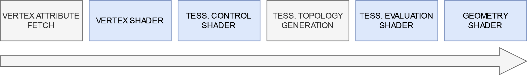
The vertex shader is required and simply transforms the vertices of your input mesh. The tesselation shader takes the mesh and sub-divides it so it becomes “denser.” You might use this to add more detail to terrain, for example. The geometry shader takes one type of primitive and outputs zero or more output primitives. A common use case for this is to render cube maps in a single pass: you duplicate your geometry six times for each cube face and transform them based on which face is being rendered.
This pipeline works for most use cases, but there are some problems.
- You have very little control over how the tesselation shader sub-divides your geometry, since it is implementation defined.
- Geometry shaders aren’t optimal for modern GPU hardware and can really slow things down if you misuse them.
- If you needed to use all three of these shader types, you might have to write four independent shaders (one vertex, two tessellation, one geometry).
Now, the mesh shading pipeline replaces all of this with a new, fully programmable pipeline that looks something like this. Again, the programmable stages are highlighted in blue:
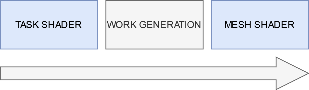
First, you have a task shader. It’s technically optional, but if you don’t need to use it, odds are you don’t need to use the mesh shading pipeline to begin with. The task shader is invoked like a compute shader, and each work group dispatches a number of mesh shader invocations. This idea of a shader dispatching other shaders is called “amplification” and is why you sometimes hear people call the task shader an “amplification shader.” The invoked mesh shaders take a payload from the task shader that invoked them, and produce some output primitives (indices and vertices).
You may or may not find this new pipeline less complicated, but it’s undeniably more powerful. Specifically, the task shader allows us to do GPU culling as described in my “GPU Driven Rendering” article, but:
- Without allocating buffers to hold output draw calls.
- With support for culling sub-regions of the mesh.
Benefit number two might not be so obvious, but I’ll explain in the next part.
Part 2: Meshlets
If you start looking into mesh shaders, you’ll hear a lot about “meshlets” or “clusters.” This is because each mesh shader can only output a fixed number of primitives and vertices, meaning you must take your mesh and subdivide it into chunks that the mesh shader can work with. In my case, I want the bounding box of my meshlets to be as small as possible because I’m going to be performing culling on each meshlet. The algorithm I used for this was inspired by Performance Comparison of Meshlet Generation Strategies by Jensen et al. Specifically, I’m using a modified implementation of their “Bounding Sphere” algorithm. The basic idea is that you start with an arbitrary triangle, and add neighboring triangles such that you minimize the new size of the bounding sphere that the meshlet creates. You can find my implementation here.
The result of the algorithm when run on the Amazon Lumberyard Bistro looks something like this (each colored patch is a meshlet):
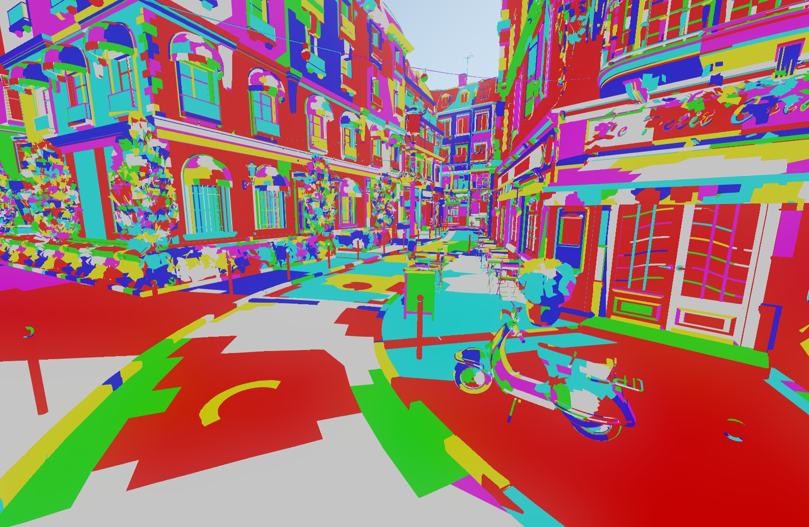
Pretty cool, right?
Part 3: The Task Shader
Now that we have a clusterized mesh, the next step is to write a task shader. I chose to have one task shader work group per object that I’m rendering. The actual GLSL task shader used by my engine is found here, but the pseudo code below should be easier to follow:
shared bool s_visible;
void main() {
    if (local_thread_id == 0) {
        s_visible = is_whole_object_visible();
    }

    barrier();

    if (!s_visible) return;

    for (meshlet in local_threads_meshlets) {
        if (meshlet.visible()) {
            add_to_output();
        }
    }

    barrier();

    if (local_thread_id == 0) {
        fill_payload();
        emit_mesh_tasks(output_meshlet_count, 1, 1);
    }
}
In essence the algorithm is:
- The first thread performs “whole object” culling to see if we can early out.
- If we didn’t early out, we distribute the meshlets among all the threads of the task shader and perform fine-grained culling.
- Finally, the first thread emits a mesh task for each passed meshlet and fills the output payload for the mesh shader.
These visibility checks are all using frustum and occlusion culling as described in the “GPU Driven Rendering” article. You can also do some fancy tricks with subgroup balloting for a bit of performance as demonstrated in the “Using Mesh Shaders for Professional Graphics” article linked at the top of the page.
Now that we’re outputting the mesh tasks, we can move on to the…
Part 4: The Mesh Shader
Mesh shader! My mesh shader is actually pretty boring, so I won’t write the pseudocode. If you’re interested, the actual GLSL shader can be found here. Essentially, all it’s doing is reading in the indices and primitives based on data passed through the payload and outputting the values in a fancy way that works well on AMD and NVIDIA hardware. What I will do, however, is describe some interesting things you could do at this stage.
- Per primitive culling: The most common way I’ve seen to do this is to assign a “view cone” to each triangle and cull primitives that are facing away from the camera. This is a bit excessive for my use case, so I didn’t include it.
- Custom tessellation: Since this stage is what outputs the primitives and vertices, you could write your own custom tessellation algorithms. I plan on doing this for my terrain and water rendering.
- Procedural geometry: Since you don’t feed in “vertex” and “index” buffers to this stage like in the traditional pipeline, you can technically use whatever data structure you want to generate your geometry. You could, for example, upload a voxel scene and generate the primitives on the GPU, like what the Nvidium Minecraft mod does. I plan on doing something like this for my particle rendering.
Conclusion
And that’s it! After implementing this in my engine, I saw about a 10% performance improvement which was honestly way more than I was expecting. The real upside to this, believe it or not, has actually been the significant reduction in complexity of my code. I was able to get rid of two whole compute shaders and replace them with a single task shader. Not to mention I don’t have to deal with storing and updating draw call buffers anymore.
There are some problems still that I’d like to fix:
- Coarse Grained Culling: In my task shader, a single thread is responsible for coarse grained culling. This is suboptimal, since all the other threads sit around doing nothing. I haven’t decided yet how I’d like to fix this. I could have each task shader work group actually be responsible for multiple objects, but this would significantly increase the size of my payload which is already pretty big. Alternatively, I could somehow distribute the work of coarse grained culling over all the threads, but I’m not confident this will improve performance by much (I’d need to test this).
- Cube Map Rendering: This was probably my biggest disappointment, and it’s not even an issue I can fix myself in a way I’d be happy with. Do you remember how I mentioned at the beginning of this article how you can use geometry shaders to render cube maps in a single pass? Well, with mesh shaders you can do this using multi-view rendering. Unfortunately, NVIDIA hardware only supports up to four multi-view render targets when using mesh shaders, meaning I can’t render all six faces of the cube in one pass (AMD hardware doesn’t have this issue). The best I can do is render the first four faces in one pass and then do the other two in another pass.